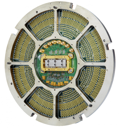
Pyramid Probe® cards are rugged, robust, and well suited for the rigors of high-performance production wafer sort. Its industry-leading signal integrity and mechanical alignment capabilities make these probe cards the perfect fit for multi-die testing for RF wireless, high-speed digital in SiPs, SoCs, and leading edge DC parametric testing.
We often get asked questions about our Pyramid Probe Cards that cover cores, boards, wafers, operations and VNA calibrations. Here are three common questions and answers:
1. Can I use a single RF line with an isolated ground as a balanced pair? (Core question)
This is not recommended. Our standard method for handling differential/balanced signaling is to provide two independent RF lines (for example RF1+ and RF1-) that are delay matched. Standard delay mismatch is ±20 ps. Custom delay matching of balanced line pairs can be designed for a delay mismatch of less than ±1.5 ps.
Using independent signal lines
for a differential pair does not force the waveform balance of an ideal,
balanced transmission line. In practice, no such ideally balanced line exists.
Standard test system practice (and the method we normally use for Pyramid Probe
cards) is to provide two matched independent signal lines and rely on the
terminations and signal sources to force signal balance. Ground currents will
approximately cancel as well as operating in a similar noise environment,
providing most of the benefit of differential signaling.
The single RF line is an
asymmetric transmission line – the signal and separate ground – and will have
differing parasitic capacitances loading the signal and ground conductors. This
results in distortion of the symmetry of the waveforms and loss of balance. A
separate 50-ohm line over a common ground performs better.
In our experience, the simplest and most robust solution is to use independent, 50-ohm lines right to the IC. Any attempt to transition to a balanced transmission line in the probe causes more harm than good. The differential drive is provided externally by the signal sources or by a balun (balanced transformer) on the PCB. For uncoupled 50-ohm transmission lines, both even and odd mode characteristic impedances are 50 ohms. This means that the differential signal is in an environment equivalent to what it experiences in a balanced transmission line. The coaxial grounds are connected to the common analog ground at the membrane. The balun or test equipment provides the connection at the other ends of the cables. Net ground currents will be equal and opposite for equal and opposite signals and will cancel.
2. Do the AC signal lines require a signal and ground contact on the wafer or just one pad? (Wafer question)
It is best to provide
ground-signal pairs at the wafer for AC lines in order to minimize ground
inductance at the probe-to-wafer interface. Ground-signal-ground is even
better. Ground inductance must be closely watched for the high-speed paths,
both for insertion loss and for crosstalk to neighboring lines that might share
ground return paths. This is particularly important for characterization
measurements such as Vector Network Analyzer (VNA) measurements.
Limiting the maximum operating frequency can mitigate these issues. In functional testing applications, it is not unusual to see several digital lines share a ground return.
3. How do I perform Two-Port VNA calibrations with my Pyramid Probe cards? (VNA calibration question)
Probe cards provide a challenge
for two-port calibration. The fixed probe spacing, often with inconveniently
oriented ports, makes it difficult to make an ideal thru calibration standard.
For two-port calibrations, a
thru standard is required. The general-purpose ISS membrane provides a number
of different length thrus, allowing connection of two ports. The electrical
behavior may not be that of an ideal thru since it may have a right-angle bend,
extra loss, or reactive stubs due to excess length. A better solution is to use
a custom designed ISS with the pad layout matching the DUT provides the best
thru layout with minimum trace bending preventing stubs. For longer thrus, it
is essential to enter the thru loss into the VNA calibration kit. The Custom ISS can be ordered at the same
time as the Pyramid Probe using the New Product Order Form (NPOF).
Best results will be obtained
for two-port Pyramid Probe calibrations using the SOLR (short-open-load-reciprocal
thru) calibration, which is available in our WinCal
VNA Calibration and Measurement software. The SOLR algorithm is not
affected by the non-ideal characteristic of the thru, and only a rough estimate
of the thru delay is required. It should
also be noted in that when the Pyramid Probe is operating in a very high cross
talk environment (crosstalk that is worse than 20 dB) it is necessary to use
SOLT (short-open-load-known thru) calibration.
The in-probe crosstalk will confuse the algorithm for doing SOLR,
resulting in gain and incorrect phase delay in the calibrated measurements.
For more information on Pyramid Probe cards, visit our website
or bookmark our
blog.