July 18, 2025
In this blog, we’ll explore the key electrical and mechanical factors that affect RF and microwave probe selection, helping you get the precision and consistency your application demands.
July 18, 2025
In this blog, we’ll explore the key electrical and mechanical factors that affect RF and microwave probe selection, helping you get the precision and consistency your application demands.
In the fast-evolving world of wafer test and high-frequency measurements, choosing the right RF or microwave probe is essential. While many engineers start by looking at a probe’s connector frequency rating, true performance at GHz and mmWave frequencies depends on much more than that.
If you’re working in semiconductor wafer test, using the wrong probe can lead to distorted results, impedance mismatches, or limited bandwidth, all of which can hurt yield and delay product development. In this blog, we’ll explore the key electrical and mechanical factors that affect RF and microwave probe selection, helping you get the precision and consistency your application demands.
1) Coaxial Connector Type Sets the Frequency Ceiling
The connector you choose sets the upper frequency limit the probe can support. Here’s a breakdown of the most common connector types and their maximum frequency ratings:
Keep in mind that 2.92 mm connectors are mechanically compatible with SMA and 3.5 mm connectors, but they operate at a reduced bandwidth. Choosing the right connector ensures your probe won’t limit the performance of your test setup.
2) Tip Configuration Directly Impacts Signal Integrity
The way the probe tip is configured, specifically how signal and ground contacts are arranged, has a big impact on signal quality and bandwidth.
Choosing a well-balanced tip configuration is one of the easiest ways to improve measurement accuracy.
3) Smaller Tip Pitch Enables Higher Frequencies
Tip pitch, the distance between probe contacts, affects how much inductance is present in the ground path. More inductance means less usable bandwidth.
When testing advanced nodes, minimizing tip pitch can help you avoid performance-limiting side effects and ensure cleaner signal paths.
4) Match the Probe to Your Application Requirements
What kind of test you’re running matters when it comes to choosing the right probe:
If you’re working on 5G, high-speed digital signals, or mmWave devices, choose a probe that goes beyond your minimum frequency requirement to keep your setup flexible and future-ready.
5) Probe Architecture Influences Coupling and Field Containment
The internal structure of the probe tip affects how the signal is transmitted and how much it interacts with neighboring lines or the device under test (DUT).
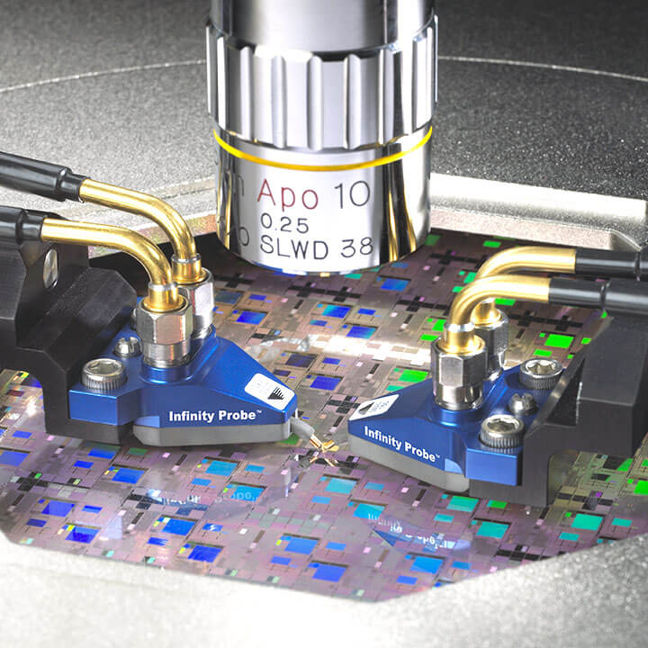
FormFactor’s Infinity Probes® stand out by using microstrip technology at the tip, something no other probe in the market currently offers. It’s a key advantage when testing advanced ICs and densely laid-out DUTs.
6) Design for Testability Early
Even the best probe won’t perform well if the DUT layout isn’t designed with testing in mind. Think about testability early in the design phase:
Working with your probe vendor early on helps you avoid late-stage layout changes and ensures your measurements are accurate from the start.
Summary: What to Consider for Accurate RF Probe Selection
When it comes to specifying a high-performance RF or microwave probe, here’s what to keep in mind:
By weighing all of these factors together, you’ll be able to select a probe that gives you clean, repeatable results across a wide range of wafer-level and mmWave testing scenarios.
Need help selecting the right probe? Contact our team or explore our Probe Selection Guide for additional guidance on high-frequency probe specifications.