When thinking about RFA arms, we refer to probe arms with the male dovetail assembly that can be paired with our modular probe positioners RPP404 and RPP504. The manual positioners, RPP404 and our RPP-404 West (W) and the motorized positioner RPP504, have a female dovetail assembly and are compatible with most of our probe stations – CM300, Elite300, Summit 200, EPS 150, EPS 200 and also the Summit 11K and 12K with a dedicated adapter.
With this modular approach, engineers can choose the manual or programmable positioner bodies; and the RFA arms for application layers, like S-parameters and load-pull. All the arms have an RF top hat version to perform dark or EMI shielded measurements, and an open Iceshield environment non-top hat version to do cold measurements.
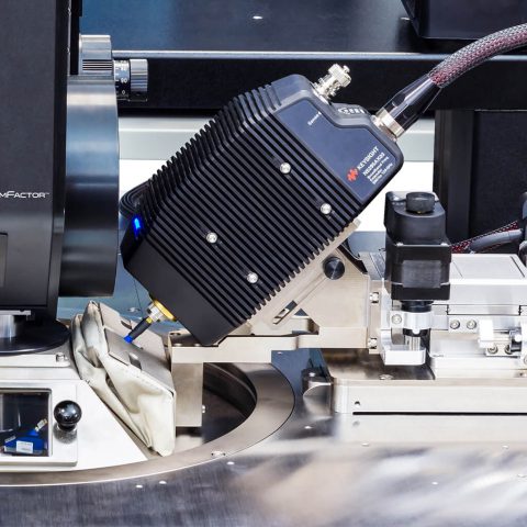
New RFA Arms for the 220 Gigahertz Broadband S- Parameter Solution
This broadband dual probe solution is a collaboration among Keysight, Dominion Microprobe, VDI and FormFactor, and allows customer to characterize their 5G and early 6G devices and transistors with a single frequency sweep from 900 Hertz to 170 or 220 Gigahertz.
These arms allow the customers to host the Keysight N5291A frequency extenders and the VDI mini extended range WR 6.5 or the WR 5.1 extenders. The DMPI T-wave probes T170 and T220 combine the waveguide and the coaxial signals into a single contact to the probe tips with an internal diplexer.
This solution was showcased this year at European Microwave Week in London and at IMS trade show in Denver, Colorado and will be also shown at the European Microwave Week in Milan at the end of September and the MWE trade show in Japan towards the end of 2022.
Like all the other RFA arms, there’s a top hat and a non-top hat version of both East and West Arms.
The Importance of Safe Handling and Storage of the RFA Arms
The frequency extenders parts like the 1-millimeter coaxial connector and the very high-frequency waveguides are fragile and can be scratched or damaged. This will result either in system performance loss or customers having to deal with costly repairs with subsequent system and tests downtime.
Many of the device modeling and device characterization engineers, need to swap regularly between different setups, either to swap frequency bands to cover a higher frequency bandwidth or swap measurement types. An example of this is to move from S-parameters to load-pull measurements to completely characterize the transistors and their devices. These procedures involve removing the extenders and the probes from the station and that’s when there is the highest risk of damage to the equipment by dropping it on the chuck or onto the platen or by accidentally bumping probe tips while removing the probes from the extenders.
So, what happens to coaxial connectors and waveguide flanges?
At these high frequencies even a tiny nick in the connectors center conductor, which could be very barely visible to the naked eye, can degrade performance. So, when disconnecting probes from cables and extenders, very special care should be taken to not damage the connectors, and one needs to avoid lateral bending force on the connector plane surface, avoid twisting the connections and properly handle the torque wrench.
It’s not ideal to do this when the probes and the extenders are still mounted on the positioner on the station above the chuck and above the platen. The same goes with the waveguides. They are frequency limited devices, but they do have more ruggedized interfaces at high frequencies compared to the coaxial connectors.
At the same time, if you do drop a waveguide extender or a connector saver and scratch and damage the flanges, this will lead to multiple problems like inaccurate alignment, poor repeatability, difficulty in restoring the flange surface and difficulty getting a perfectly flat connection leading to performance loss.
When changing measurement setups, these are the commonly-used steps:
1. Remove the probes while on the station. These can be difficult to access with a torque wrench and there is a chance to damage the equipment and to hit the probe tips.
2. Remove the waveguides and cables. This increases the risk of dropping the screws, adapters, and small cables inside the prober.
3. Remove the extender or the tuner or both in some cases.
A Safer Way to Change Measurement Setups
There is a new, safer way of changing the measurement setups, and this is represented by recently introduced RFA arm storage pods that allow fully populated RFA arms, configured with probes, to be stored safely and be ready for quick band swapping from one frequency band to another.
Storage pods include a hinged, anti-static, clean room-safe window cover in the front which can be moved forward to load the RFA arm in and then backwards to protect the probe tip from anything getting dropped onto it. This is made out of transparent material so you can still look down and inspect the probe tip from above.
There’s also a slot that is designed for the power supply for the frequency extenders to be mounted in the storage pod, on the probe arm, and still maintain the operating temperature when not in use.
To view examples of our storage pods, visit our website.